Cost Effective Industrial Wifi

Now available in stock – JAYCOR offers a complete end-to-end solution for cost-effective industrial/outdoor ruggedized Wifi. Purchase all components for a turnkey solution:

  • Wireless AP (Access Point)
  • Omni or directional antennas
  • Antenna (N-Type) & Ethernet (RJ45) patch cords
  • Antenna & Ethernet lighting surge protection
  • Din Rail /Wall Mount PoE Switches, Media Converters and SFP modules
  • Din Rail Power Supplies & cabtyre
  • Outdoor enclosure


Empower your Data Centre Collocation Customers with PatchPro® Web

Real-time Online Access to Hosted Infrastructure

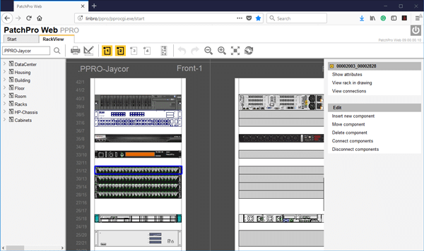
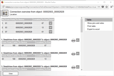
PatchPro® Web application provides a collocation data centre’s clients access to their hosted infrastructure, online through a user-friendly web interface. An amazing tool for empowering DC customers to access and view their network infrastructure, servers and other devices. View free ports and rack units, create patch or cross-connects between devices and send workorders direct to the NOC.

The results:

  • Provide Visibility
  • Improve Efficiency
  • Empower Customers

Web Features

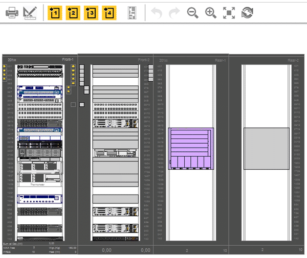
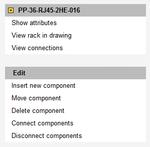
Front (and back) and rear (and back) views provide full visibility of all hosted infrastructure within the rack.

– user level access restricts collocations customers from accessing and viewing other customers infrastructure.

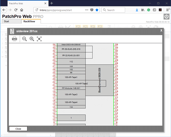
Side rack view provides visibility in ensuring no conflicting space requirements apply, when adding additional hardware components.

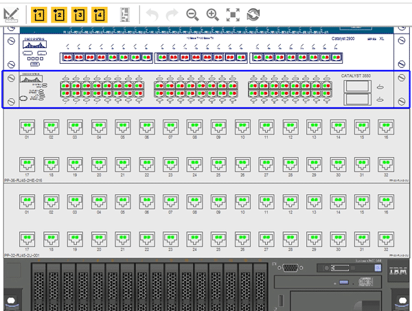
Visualize connections in granular detail:

– Connected/open ports (front and back) visually

– All connected devices

– Export to Excel/Visio

Customers manage their infrastructure and connectivity

– Components (Servers, switches, SFP’s)

– Create Connections (Patches & Cross-Connects)

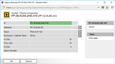
Access unique attributes for all connected devices


Additional Benefits of PatchPro® SaaS

  • SaaS (Software as a service)
    • No capital investment in licensing, hardware, staff and training required to execute
    • Contract based on your scope of work and customized for your requirements and budget
  • Open API

Other Modules (Included)

  • PactchPro® F – Facilities Manager
    • Infrastructure physical Layer management (iPLM)
  • PatchPro®I – Infrastructure Connection Manager
    • Data Centre Infrastructure management (DCIM)
    • Automated Infrastructure Management (AIM)
  • PatchPro® SPM Web
    • Service Plan Manager/Asset Managment


Greg Pokroy

CEO – JAYCOR International

Network Upgrades: Utilizing Parallel Fiber Cabling

It comes to no surprise, that enterprise and consumer demands are impacting data centers and networks. As speed requirements go up, layer 0 (the physical media for data transmission) becomes increasingly critical to ensure link quality.

Numerous organizations are looking for an economical, futureproof migration path toward 100G (and beyond). Multimode fiber (MMF) cabling systems continue to be the most popular, futureproof cabling and connectivity solution.

Both duplex and parallel cabling are options for network upgrades. A few weeks ago, we discussed duplex MMF cabling. In this, we’ll discuss parallel MMF cabling.


Parallel Fiber Cabling

When transceiver technology can’t keep up with Ethernet speed requirements, the most obvious solution is to move from duplex to parallel fiber cabling.

Although using BiDi (bi-directional) and SWDM (shortwave wavelength division multiplexing) transceivers can reduce direct point-to-point cabling costs, they do not support breakout configuration (e.g. 40G switch ports to four 10G server ports), which is a very common use in data centers.

According to research firm LightCounting, approximately 50% of 40GBASE-SR4 QSFP+ form factors are deployed for breakout configuration; the other 50% are deployed for direct switch-to-switch links.

As a matter of fact, 40G QSFP+ and 100G QSFP28 are the most popular form factors used for Ethernet switches in data centers. QSFP (quad small form-factor) is a bi-directional, hot-pluggable module mainly designed for datacom applications. QSFP+/QSFP28 has a 2.5x data density compared to SFP+/SFP28, using four parallel electrical lanes. The optical interface is a receptacle for MPO female connectors. Four fibers (1, 2, 3 and 4) transmit the signal; the other four fibers (9, 10, 11 and 12) receive the optical signal.

QSFP transceivers, paired with parallel fiber connectivity with a one-row MPO-12 (Base-8 or Base-12) interface, can support flexible breakout or direct connection.

  • 40G/100G direct links are typically used in switch-to-switch links, which can be supported by duplex or parallel fiber cabling.
  • 40G/100G Ethernet ports can be configured as 4x 10G or 4x 25G ports to support 10G/25G server uplinks.
  • 40G/100GBASE-SR4 transceivers only use eight fiber threads in an MPO-12 connector; therefore, Base-8 is a cost-optimized cabling solution that allows 100% fiber utilization.

Read full article

Public vs Private Clouds: How Do You Choose?

An Intel Security survey of 2,000+ IT professionals last year revealed several fascinating information about public and private cloud adoption. For starters, within the next 15 months, 80% of all IT budgets will have some income dedicated to cloud solutions.

Many enterprises are starting to rely on public and private clouds for a few simple reasons:

  • Most good public and private cloud providers regularly and automatically back up data they store so it is recoverable if an incident occurs.
  • Tasks like software upgrades and server equipment maintenance become the responsibility of the cloud provider.
  • Scalability is virtually unlimited; you can grow rapidly to meet business needs, and then scale back just as quickly if that need no longer exists.
  • Upfront costs are lower, since cloud computing eliminates the capital expenses associated with investing in your own space, hardware and software.

But before you decide you are moving to the cloud, you should know the differences between public and private clouds. Making a choice between public and private clouds often depends on the type of data you’re creating, storing and working with.


Public Clouds Defined

The public cloud got its kick start by hosting applications online – today, however, it has evolved to include infrastructure, data storage, etc. Most people do not  realise that they have been benefitting from the public cloud for years (before most of us even referred to “public and private clouds”). For example, any time you access your online banking tool or login to your Gmail account, you’re using the public cloud.

In a public cloud, data center infrastructure and physical resources are shared by many different enterprises, but owned and operated by a third-party services provider (the cloud provider). Your company’s data is hosted on the same hardware as the data from other companies. The services and infrastructure are accessible online. This allows you to quickly scale resources up and down to meet demand. As opposed to a private cloud, public cloud infrastructure costs are based on usage. When dealing with the public cloud, the user/customer typically has no control (and very limited visibility) regarding where and how services are hosted.


Private Clouds Defined

In a private cloud, infrastructure is either hosted at your own onsite data center or in an environment that that can guarantee 100% privacy (through a multi-tenant data center or a private cloud provider). In these third-party environments, the components of a private cloud (computing, storage and networking hardware, for example) are all dedicated solely to your organization so you can customize them for what you need. In some cases, you’ll even have choices about what type of hardware is used. No other organization’s data will be hosted using the equipment you use.

With an internal private cloud (one hosted at your own data center), your enterprise incurs the capital and operating costs associated with establishing and maintaining it. Many of the benefits listed earlier about choosing cloud services don’t apply to internal private clouds, especially since you serve as your own private cloud provider.

In organizations and industries that require strict security and data privacy, private clouds usually fit the bill because applications can be hosted in an environment where resources aren’t shared with others; this allows higher levels of data security and control as compared to the public cloud.


What’s a Hybrid Cloud?

Enterprises also have the opportunity to take advantage of both the public and private cloud by implementing a hybrid cloud, which combines the two.

For example, the public cloud can be used for things like web-based email and calendaring, while the private cloud can be used for sensitive data.

Read full article

Network Cables; How Cable Temperature Impacts Cable Reach

There is nothing more disheartening than making a big investment in something that promises to deliver what you require – only to find out once it is too late that it is not performing according to expectations. What happened? Is the product not adequate? Or is it not being utilised correctly?

Cable Performance Expectations

This scenario holds true with category cable investments as well. A cable that can not fulfil its 100 m channel reach (even though it is marketed as a 100 m cable) can derail network projects, increase costs, cause unplanned downtime and call for lots of troubleshooting (especially if the problem is not obvious right away).

High cable temperatures are sometimes to blame for cables that don’t perform up to the promised 100 m. Cables are rated to transmit data over a certain distance up to a certain temperature. When the cable heats up beyond that point, resistance and insertion loss increase; as a result, the channel reach of the cable often needs to be de-rated in order to perform as needed to transmit data.

Many factors cause cable temperatures to rise:

  • Cables installed above operational network equipment
  • Power being transmitted through bundled cabling
  • Uncontrolled ambient temperatures
  • Using the wrong category cabling for the job
  • Routing of cables near sources of heat

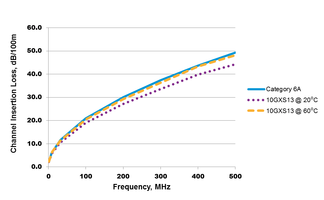
In Power over Ethernet (PoE) cables – which are becoming increasingly popular to support digital buildings and IoT – as power levels increase, so does the current level running through the cable. The amount of heat generated within the cable increases as well. Bundling makes temperatures rise even more; the heat generated by the current passing through the inner cables can’t escape. As temperatures rise, so does cable insertion loss, as pictured below.

Testing the Impacts of Cable Temperature on Reach

To assess this theory, I created a model to test temperature characteristics of different cables. Each cable was placed in an environmental chamber to measure insertion loss with cable temperature change. Data was generated for each cable; changes in insertion loss were recorded as the temperature changed.

The information gathered from these tests was combined with connector and patch cord insertion loss levels in the model below to determine the maximum length that a typical channel could reach while maintaining compliance with channel insertion loss.

This model represents a full 100 m channel with 10 m of patch cords and an initial permanent link length of 90 m. I assumed that the connectors and patch cords were in a controlled environment (at room temperature, and insertion loss is always the same). Permanent links were assumed to be at a higher temperature of 60 degrees C (the same assumption used in ANSI/TIA TSB-184-A, where the ambient temperature is 45 degrees C and temperature rise due to PoE current and cable bundling is 15 degrees C).

Using the data from these tests, I was able to reach the full 100 m length with Belden’s 10GXS, a Category 6A cable. I then modeled Category 6 and Category 5e cables from Belden at that temperature, and wasn’t able to reach the full 100 m. Why? Because the insertion loss of the cable at this temperature exceeded the insertion loss performance requirement.

Read full article

Which is Right for You: 40G vs 100G Ethernet?

Companies like as Google, Amazon, Microsoft and Facebook started their migration toward 100G in 2015 – and smaller enterprise data centers are now following suit. Plenty of these new 100G deployments adopt a singlemode fiber solution for longer reach that best suits their hyperscale data center architectures.

Comparing 40G vs. 100G optical transceivers currently available in the market, both have been developed and cost optimized for their designated reach and applications.

While weighing 40G vs. 100G Ethernet, and deciding which migration path makes more sense for your organization, here are some facts you should know:

  • Switches with 10G SFP+ ports, or 40G (4x 10G) QSFP+ ports, can support 10G server uplinks
  • Switches with 25G SFP28 ports, or 100G (4x 25G) QSFP28 ports, can support 25G server uplinks
  • 100G switches have already been massively deployed in cloud data centers; the cost difference between 40G vs. 100G is small
  • Most new 100G transceivers can easily support 40G operation
  • Some non-standard 100G singlemode transceivers are designed and optimized for cloud data center deployment; product availability for other environments is limited for the short term
  • Traditional Ethernet networking equipment giants Cisco and Arista have already started selling switch software on a standalone basis that goes into networking devices (such as a “white box” solution with merchant switch ASICs); this move accelerates hardware and software disaggregation and lowers overall ownership costs for end-users
  • According to Dell’Oro, 100G switch port shipments will surpass 40G switch port shipments in 2018.

When considering system upgrades from 10G, it’s essential to understand that 40G will also be needed to support the legacy installed base with 10G ports; 40G/100G switch port configurability will certainly accelerate 100G adoption in the enterprise market.

In 2017, 100G Ethernet is already ubiquitous – it will be mainstream, not just in hyperscale cloud data centers. Next-wave 200G/400G Ethernet will soon hit the market; standards bodies have already initiated a study group for 800G and 1.6T Ethernet to support bandwidth requirements beyond 2020.

Wrapping Up the Road to 800G

We’re almost finished with our blog series covering the road to 800G Ethernet. Subscribe to our blog to follow this series, as well as receive our other content each week. As part of this blog series, we’ve covered the following topics:


Read full article

Expectation for Fiber Connectivity: Layer 0

The footprints of cloud data centers continue to increase substantially to accommodate massive amounts of servers and switches. To support sustainable business growth, many Web 2.0 companies, such as Google, Facebook and Microsoft, have decided to deploy 100G Ethernet using single mode optics-based infrastructure in their new data centers.

According to LightCounting and Dell’Oro, 100G transceiver module and switch port shipments this year will outpace last year’s shipments, with 10 times as many being shipped in 2017 vs. 2016. Shipment for 200G/400G switch ports will begin in 2018.

Data Center Architecture and Interconnects

Most intra-rack fiber connectivity has been implemented with DAC (direct-attach cables). As we discussed in our fiber infrastructure deployment blog series, system interconnects with a reach longer than 5 m must use more fiber connectivity to achieve the desired bandwidth.

100G, 200G, and 400G transceivers for data center applications have already been showcased by various vendors; massive deployment is expected to start in 2018. Based on reach requirements, different multimode and signal optical transceivers are being developed with optimized balance between performance and cost. Examples include:

  • In-room or in-row interconnects with multimode optics or active optical cables (AOCs), with a reach of up to 100 m. (New multimode transceivers, such as 100G-eSR4, paired with OM4/OM5 multimode fiber, can support a maximum reach of up to 300 m for 100G connectivity, which is suitable for most intra-rack interconnects.)
  • On-campus interconnects (inside the data center facility), with transceiver types such as PSM4 (parallel singlemode four-channel fiber) or CWDM4/CLR4 (coarse wavelength division multiplexing over duplex singlemode fiber pair) for 500 m reach.
  • On-campus interconnects (between data center buildings), with transceiver types such as PSM4 and CWDM4/CLR4 for a reach of 2 km.
  • Regional data center cluster interconnects, also referred as data center interconnects (DCIs), using coherent optics (CFP2-ACO and CFP2-DCO) for a reach of over 100 km, or direct modulation modules, such as QSFP28 DWDM ColorZ, for reach of up to 80 km.

Multimode Fiber Roadmap to 400G and Beyond

Multimode optics use low-cost VCSELs as the light source. When compared to singlemode transceivers, which utilize silicon photonics, VCSELs have some native performance disadvantages:

  • Fewer available wavelengths for wavelength division multiplexing
  • Speed is limited by the singlemode laser
  • Less advanced modulation options
  • High fiber counts needed to deliver required bandwidth
  • Shorter reach in multimode fiber (limited by fiber loss and dispersion) compared to singlemode fiber

Read full article

Better, Faster, Cheaper Ethernet: The Road From 100G to 800G

Worldwide IP traffic has been increasing immensely in the enterprise and consumer division, driven by growing numbers of Internet users, as well as growing numbers of connected devices that provide faster wireless and fixed broadband access, high-quality video streaming and social networking capabilities.

Data centers are expanding globally to support computing, storage and content delivery services for enterprise and consumer users. With higher operation efficiency (CPU usage), higher scalability, lower costs and lower power consumption per workload, cloud data centers will process 92% of overall data center workloads by 2020; the remaining 8% of the workload will be processed by traditional data centers.

According to the Cisco Global Cloud Index 2015-2020, hyperscale data centers will grow from 259 in 2015 to 485 by 2020, representing 47% of all installed data center servers.

Cisco Global Cloud Index

Source: Cisco

Global annual data center traffic will grow from 6.5 ZB (zettabytes) in 2016 to 15.3 ZB by 2020. The majority of traffic will be generated in cloud data centers; most traffic will occur within the data center.

When it comes to supporting cloud business growth, higher performance and more competitive services for the enterprise (computing and collaboration) and consumers (video streaming and social networking), common cloud data center challenges include:

  • Cost efficiency
  • Port density
  • Power density
  • Product availability
  • Reach limit
  • Resilience (disaster recovery)
  • Sustainability
  • System scalability

This is the first in a series of seven blogs that will appear throughout the rest of 2017; in this series, we’ll walk you down the road to 800G Ethernet. Here, we take a close look at Ethernet generations and when they have (or will) come into play.

Read full article

Ethernet Switch Evolution: High Speed Interfaces

Technology development has always been driven by emerging applications: big data, Internet of Things, machine learning, public and private clouds, augmented reality, 800G Ethernet, etc.

Merchant Silicon switch ASIC chip development is an excellent example of that golden rule.


OIF’s Common Electrical Interface Development

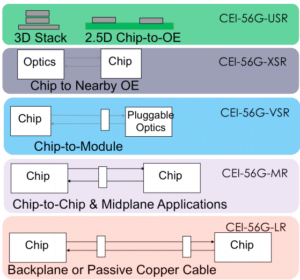
The Optical Internetworking Forum (OIF) is the standards body – a nonprofit industry organization – that develops common electrical interfaces (CEIs) for next-generation technology to ensure component and system interoperability.

The organization develops and promotes implementation agreements (IAs), offering principal design and deployment guidance for a SerDes (serializer-deserializer), including:

  • CEI-6G (which specifies the transmitter, receiver and interconnect channel associated with 6+ Gbps interfaces)
  • CEI-11G (which specifies the transmitter, receiver and interconnect channel associated with 11+ Gbps interfaces)
  • CEI-28G (which specifies the transmitter, receiver and interconnect channel associated with 28+ Gbps interfaces)
  • CEI-56G (which specifies the transmitter, receiver and interconnect channel associated with 56+ Gbps interfaces)

OIF’s CEI specifications are developed for different electrical interconnect reaches and applications to ensure system service and connectivity interoperability at the physical level:

  • USR: Ultra-short reach, for < 10 mm die to optical engine within a multi-chip module (MCM) package.
  • XSR: Extremely short reach, for < 50 mm chip to nearby optical engine (mid-board optics); or CPU to CPU/DSP arrays/memory stack with high-speed SerDes.
  • VSR: Very short reach, < 30 cm chip (e.g. switch chip) to module (edge pluggable cage, such as SFP+, QSFP+, QSFP-DD, OSFP, etc.).

Read full article

Time Sensitive Networking – 3 Benefits it Will Bring to Railway Communication

As demand for mass transit expands in densely populated urban areas, so do passenger demands for more entertainment, on-time delivery and safety. The Industrial Internet of Things (IIoT) and impending technologies like Time-Sensitive Networking (TSN) are making this feasible.

TSN is a novel technology, currently in development at the Institute of Electrical and Electronics Engineers (IEEE), that provides an entirely new level of determinism in standard IEEE 802.1 and IEEE 802.3 Ethernet networks. Standardizing Ethernet networks with TSN will deliver an important capability: deterministic, time-critical packet delivery.

It represents the next measure in the evolution of dependable and standardized automation technology and is certainly the next step in improving railway communication.

Time-Sensitive Networking Will Be Key for Railway Communication

Communication-based train control (CBTC), which uses wireless technologies to continually monitor and control the position of trains, could use TSN to guarantee real-time delivery of critical safety data on Ethernet networks also carrying non-safety related data. Ethernet networks standardized with TSN will support higher data bandwidths and reduce the number of devices required for railway communication. Ultimately, with more information being transmitted across railway Ethernet networks, TSN will ensure that the most critical data is prioritized to assure operations.

What does railway communication look like today, without TSN? The process is like a police car and a truck sharing a one-lane road: Imagine that a truck, (which represents non-time-critical information), is driving along a one-lane road and can’t see anybody behind or in front of him on the road. So, he drives the truck onto the next section of the road. But just as the truck enters this section, a police car (representing time-critical information) with emergency lights arrives and wants to overtake the truck to quickly reach an emergency situation further down the road. unfortunately, the truck has already turned onto the next section of the one-lane road and cannot move out of the way, causing an unexpected delay to the police car!

Read full article

Copyright © 2024 Jaycor International
Engineered by: NJIN Agency